

Introduction:
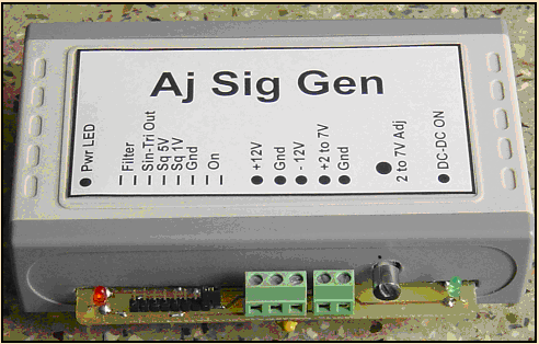
This USB connected unit implements a microcontroller based DDS Signal Generator providing Sin and Triangular waveforms with adjustable magnitude and offset up to 50 kHz. TTL and 1 V square waves are simultaneously provided. Additionally ± 12V and a variable +2 to 7V output with a total capacity of 1W is provided to power external circuits under test.
Block Schematic and Function Description
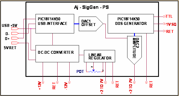
The figure shows the simplified block schematic of the system. For ease of portability the unit is powered and controlled from the USB port of a PC.
Two PIC18F14K50 microcontrollers are used to provide the functionality of the unit.
The first PIC microcontroller implements the following functions:
Two PIC18F14K50 microcontrollers are used to provide the functionality of the unit.
The first PIC microcontroller implements the following functions:
· Communicates with the host PC for enumeration as a USB to UART device
· Sets up the unit as a 500mA device
· Switches on power to the DC-DC converter
· Provides the complimentary square wave drive to the DC-DC converter
· Acts as a USB communication interface to the second PIC
· Provides the Amplitude reference for DAC2
· Provides the digital word for DAC1 giving the offset value.
The second PIC microcontroller implements the remaining DDS functions
· Direct Digital Synthesis (DDS) signal generation
· Sin/ triangle word output to DAC2
· TTL and 1 V square reference output
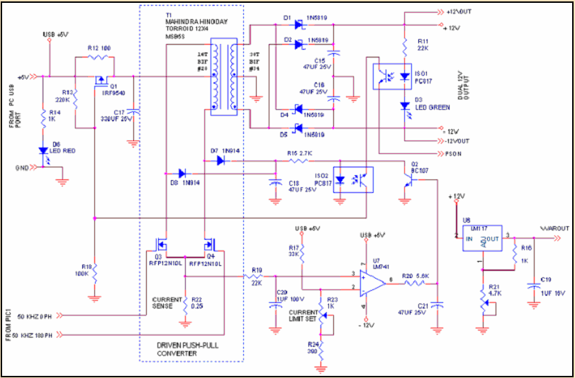
The DC-DC converter is a driven 1W, 5V to ± 12V operating at 100 kHz. The +12 V output is fed to a linear regulator to provide a variable +2 to 7 V output controlled by a variable potentiometer.
The DC-DC converter provides full protection to the host PC USB port as its outputs are short circuit and current limit protected.
The circuit under test can be rigged up on a standard breadboard and powered from the power sockets provided.
The DC-DC converter provides full protection to the host PC USB port as its outputs are short circuit and current limit protected.
The circuit under test can be rigged up on a standard breadboard and powered from the power sockets provided.
Software on the PC Host:
A Visual Basic .Net 2.0 based GUI program is used to control the functions of the Aj-SigGen - PS unit. An Aj_SigGen.exe along with associated USB driver files has been tested for compatibility with Windows XP and Windows 7 with .net 2.0.
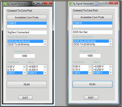
The GUI based Windows software on the Host PC permits checking for available COM ports and connecting to the port on which the hardware is connected.
Once connected the hardware unit responds with a ready signal.
Waveform type, frequency, amplitude and offset can be set using the simple controls.
The RUN button initiates the signal output and indicates the waveform set.
An EXIT button is provided to close the program and exit.
Once connected the hardware unit responds with a ready signal.
Waveform type, frequency, amplitude and offset can be set using the simple controls.
The RUN button initiates the signal output and indicates the waveform set.
An EXIT button is provided to close the program and exit.
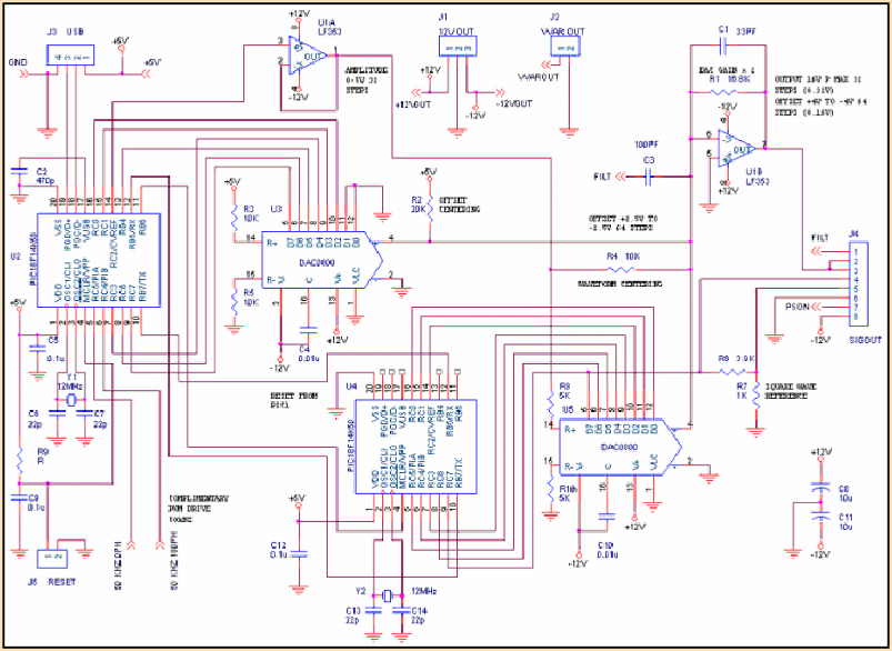
Circuit Diagram of USB interface and DDS signal generation
Circuit diagram of USB powered DC-DC converter
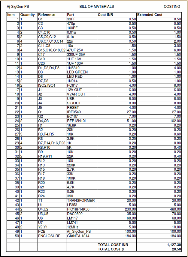
Bill of Materials
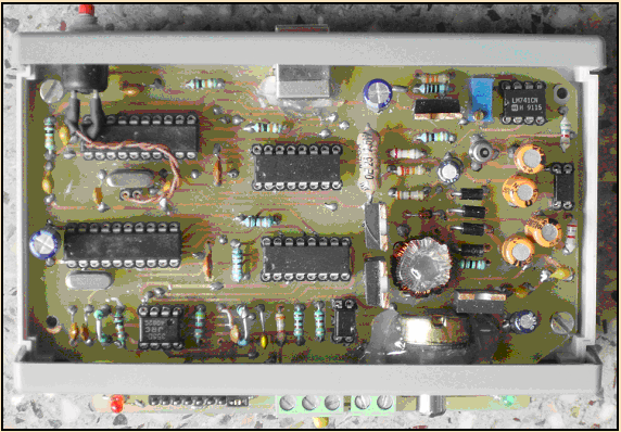
Component Layout
Software, PCB's and Documentation
Complete documentation and the software executive files are provided in
Aj_SigGen_PS SW and Docs.rar
Contains:
1. The Technical manual Aj-SigGen-PS_Tech-Manual-Final.pdf
2. A Folder of the VB.Net files Aj_SigGen_Windows_Net2
Containing
Aj_SigGen.exe
Aj_SigGen.pdb
Aj_SigGen.xml
SigGen2.ICO
3. The fuze.hex for the first pIC PIC1_USB.hex
4. The fuze.hex for the second pic Aj-SigGen.hex